High-frequency magnetic characterization is accurate only when the measurement itself keeps pace with the material. This project turns a traditionally manual resonant test into a fully automated, high-throughput measurement platform.
Why automate resonant measurements?
Core loss strongly influences the efficiency, temperature, and size of high-frequency power converters. Resonant methods can characterize this loss accurately, but conventional testing requires repeated capacitor replacement, frequency tuning, oscilloscope capture, and FFT processing. The procedure is slow, equipment-dependent, and vulnerable to thermal drift.
The proposed system automates the entire sequence: capacitor selection, resonance search, drive-level sweep, fundamental-component extraction, and loss calculation.
The system in three layers
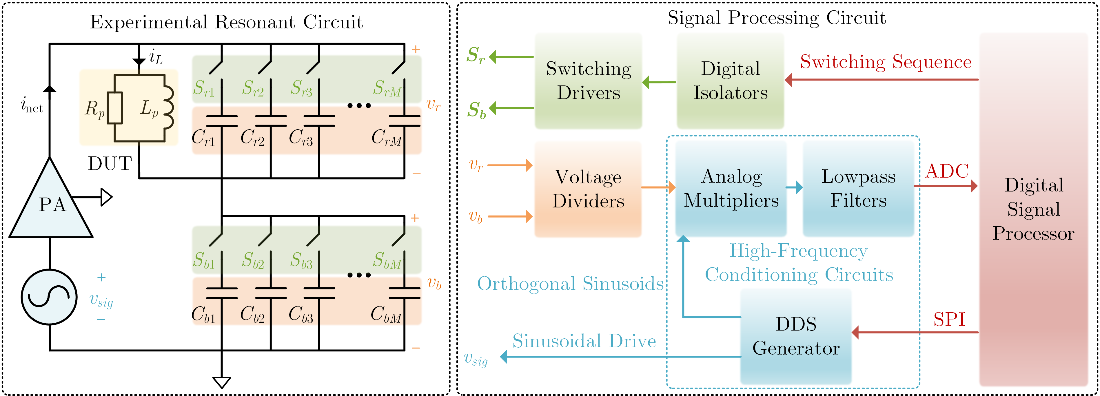
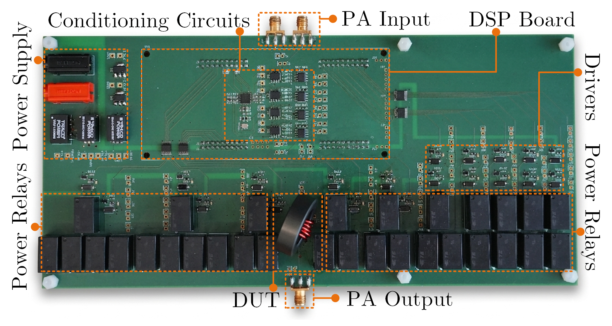
- Digitally switched capacitor sequences reconfigure both the resonant and blocking capacitances, allowing the operating frequency to sweep without manual component replacement.
- High-frequency analog conditioning circuits extract the magnitude and phase of the fundamental signals directly, avoiding oscilloscope-based FFT processing.
- A local DSP controller commands the waveform generator and relays, fine-tunes resonance at every operating point, and calculates flux density and volumetric core loss.
The dual capacitor banks each contain ten independently controlled branches. In principle, this provides up to $2^{10}$ capacitance configurations while retaining the high sensitivity of the resonant method.
Accuracy across magnetic materials
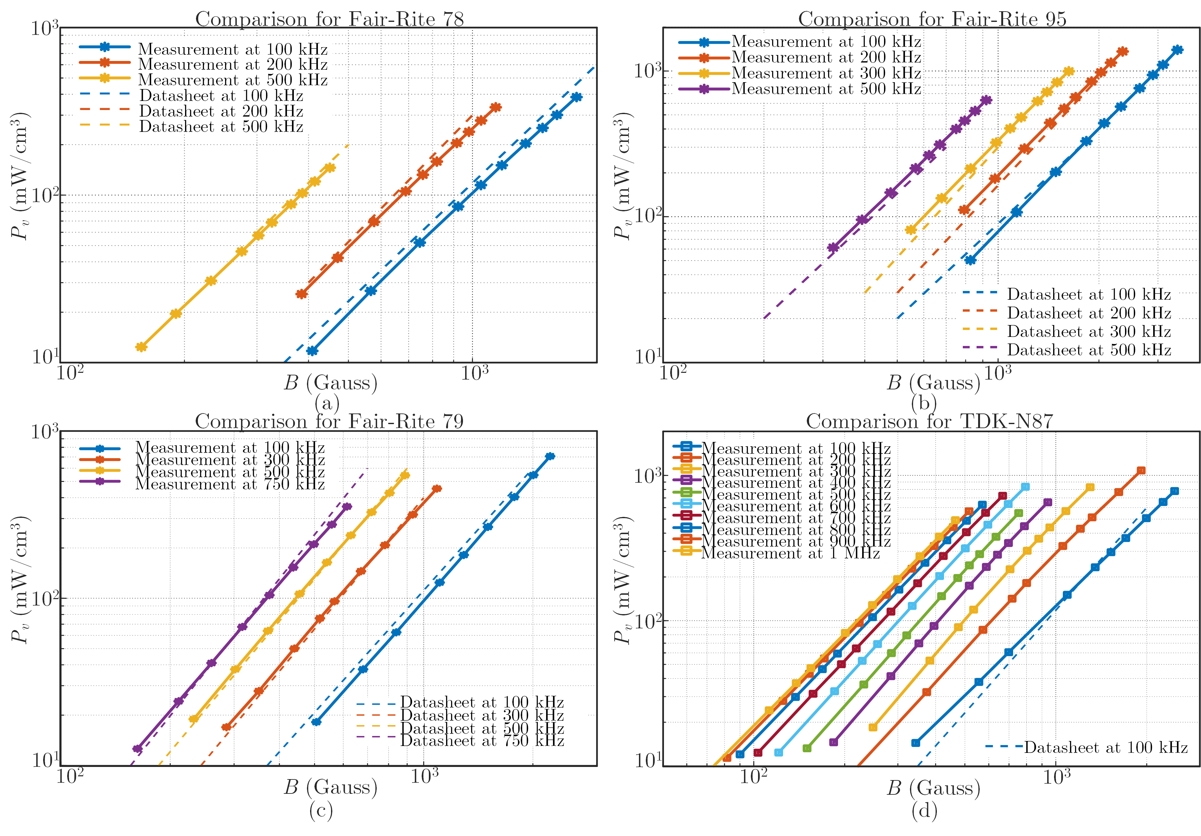
The prototype was evaluated at 25 degrees Celsius using Fair-Rite 78, Fair-Rite 95, Fair-Rite 79, and TDK N87 ferrites over frequencies reaching 1 MHz. Measured loss curves closely follow the manufacturers’ reference data across a wide range of flux density.
Most acquired points remain within a ±5% error band, while the maximum observed deviation from the datasheet values is approximately 13%. This agreement shows that automation does not trade away the accuracy of the underlying resonant technique.
High-throughput data acquisition
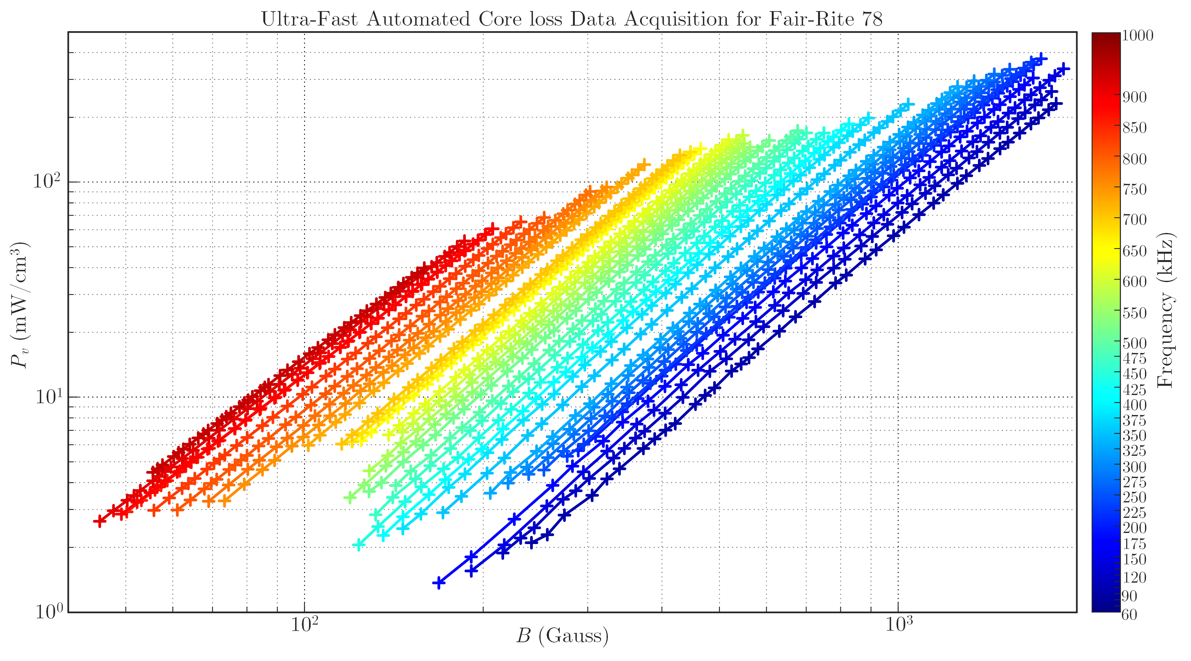
For Fair-Rite 78, the system swept 33 frequencies from 60 kHz to 1 MHz and evaluated 40 drive points at each frequency. The complete map contains 1,320 valid measurements collected in only 20 seconds.
That is approximately 4,000 times faster than a skilled operator taking one manual point per minute, and about 450 times faster than a previously reported automated resonant platform. Rapid acquisition also limits device self-heating, helping keep material conditions consistent throughout a sweep.
High throughput changes what can be studied. Instead of collecting only a few representative points, an engineer can map a dense loss surface, repeat a sweep to quantify variation, or gather enough consistent data for regression and machine-learning models. Because excitation search and signal extraction use the same automated sequence, comparisons among materials are less dependent on operator timing and oscilloscope settings.
Why it matters
The main contribution is a repeatable measurement pipeline, not simply a faster instrument. By combining resonant accuracy with hardware-controlled sweeping and local signal processing, the system can generate large, consistent datasets for magnetic design and data-driven loss modeling.
The present relay implementation targets the sub-MHz range. The architecture itself can scale toward higher frequencies as switching devices with lower on-state resistance and off-state capacitance become available.