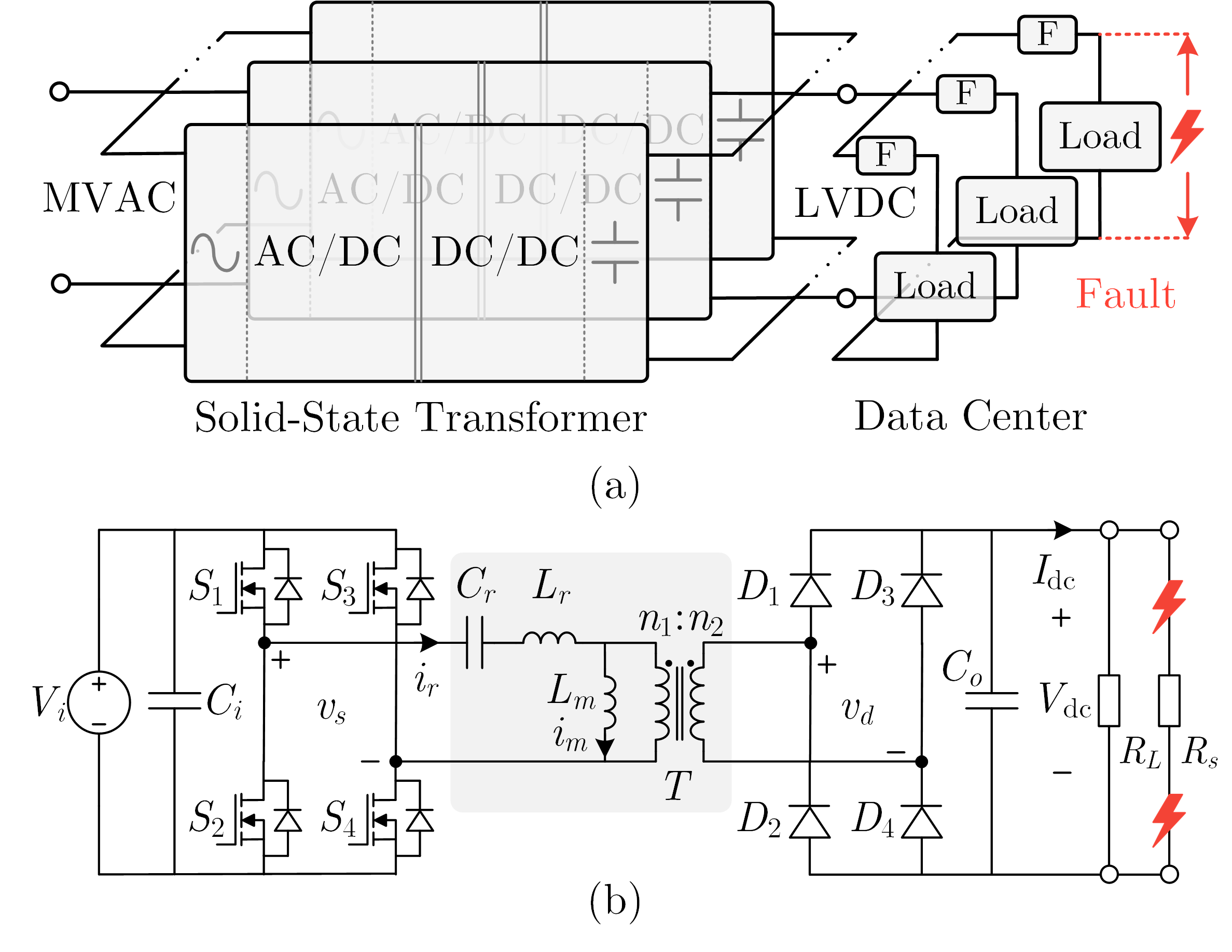
As data centers move toward medium-voltage AC to low-voltage DC power architectures, solid-state transformers must do more than convert power efficiently: they must keep healthy loads operating when one branch develops a short circuit. This project gives the LLC DC-DC stage that fault-ride-through capability through control alone.
Why a conventional shutdown is not enough
An LLC converter normally behaves as a tightly regulated voltage source. During a downstream short circuit, that behavior becomes dangerous: the controller attempts to support a collapsing bus while the resonant and output currents rise within tens of microseconds. Simply shutting down the entire converter protects the hardware, but it also removes power from healthy branches and can turn a local rack fault into a wider outage.
Selective protection needs a different response. The converter must suppress the initial current spike, then deliberately supply a bounded current long enough for a fuse or circuit breaker to isolate only the faulted branch.
A four-stage control response
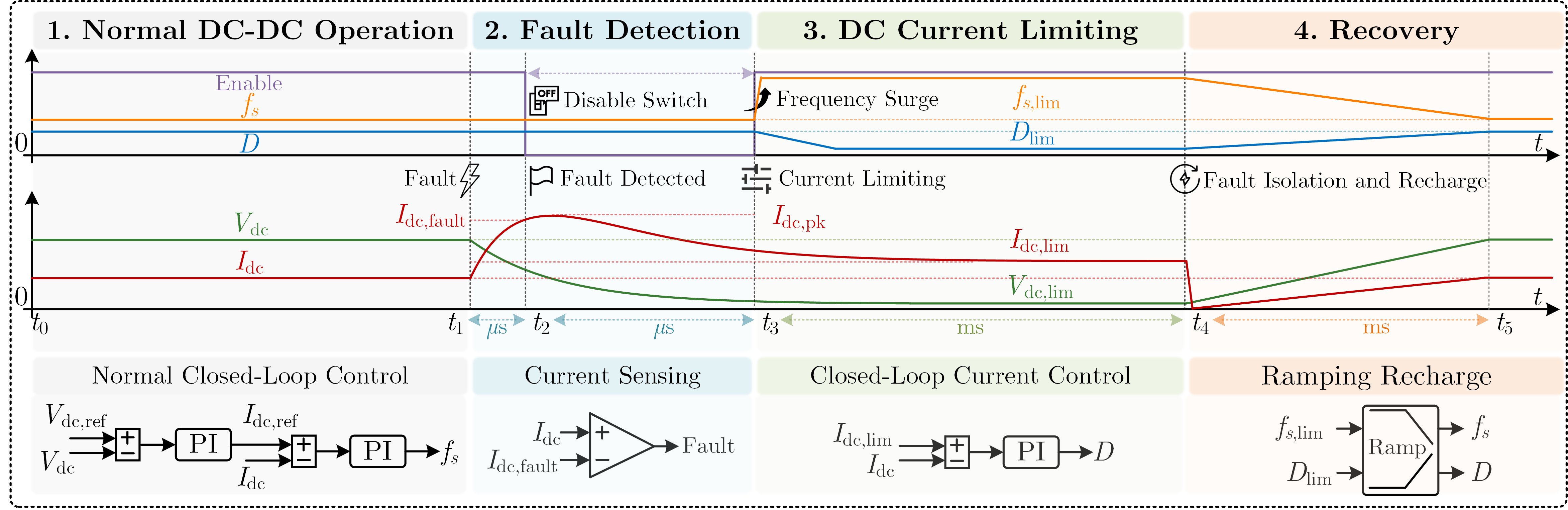
The proposed strategy is embedded in the local digital controller and coordinates four operating stages:
- Normal operation regulates the 400 V DC bus using the converter’s existing voltage and current loops.
- Fault detection combines output-current magnitude with its rate of rise. Once the threshold is crossed, the switches are disabled for one switching cycle to arrest the initial surge.
- Current limiting raises the switching frequency from the 154 kHz resonant point to 300 kHz, reducing power transfer immediately. A dedicated duty-cycle loop then regulates the fault current at the selected 15 A level while downstream protection clears the branch.
- Recovery ramps frequency and duty cycle back to their nominal values, recharging the DC bus gradually instead of reconnecting it with a damaging inrush current.
Experimental verification
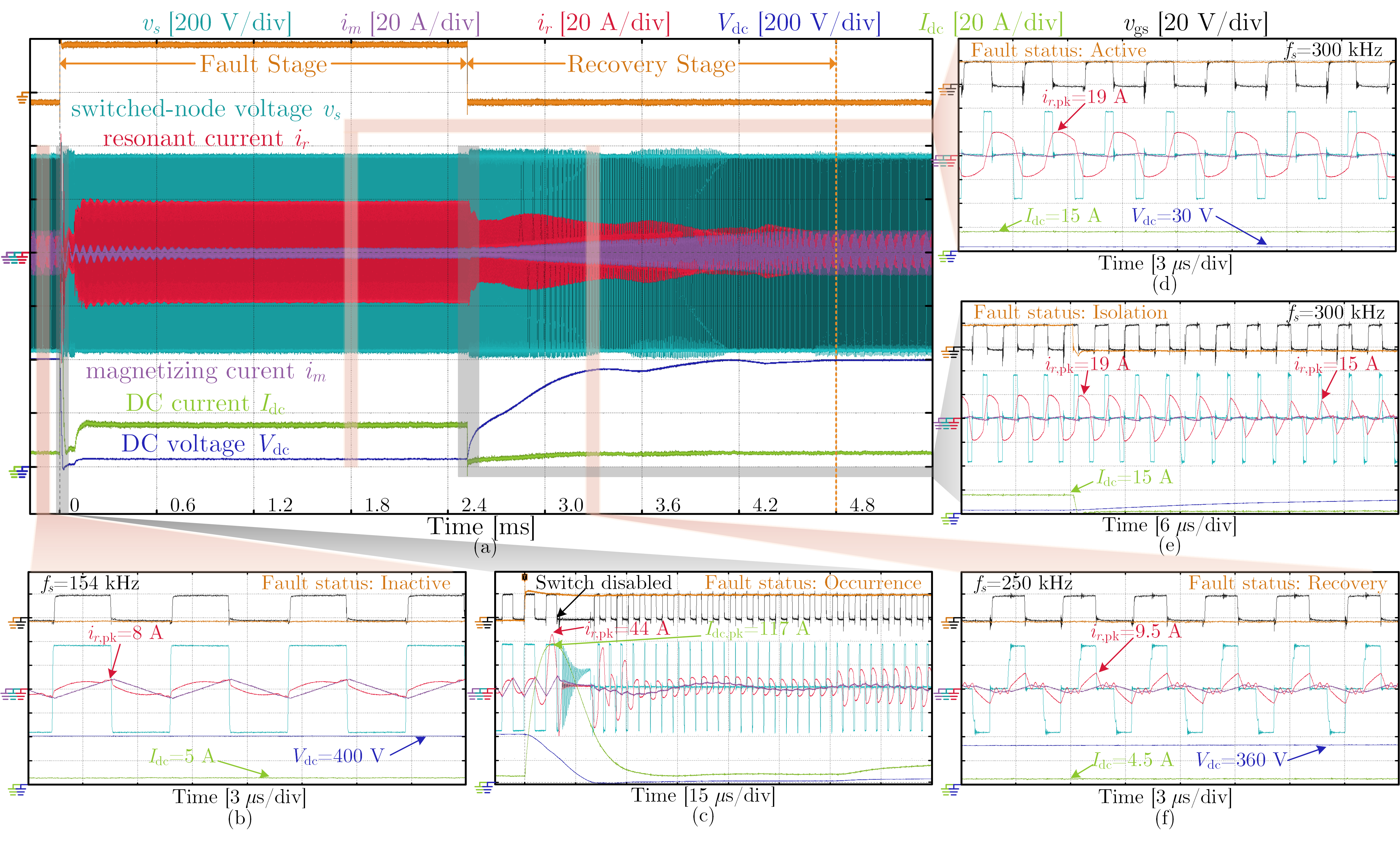
The strategy was tested on a 2 kW LLC converter with 400 V input and output, a 154 kHz resonant frequency, and a 2 ohm resistance emulating a load-side short circuit. Without intervention, the DC fault current reached 117 A and the resonant current reached 44 A within 10 microseconds.
After detection, the controller prevented further escalation and transitioned into regulated current limiting. The output settled at 15 A and approximately 30 V for several milliseconds, providing controlled energy for a protection device to operate. Once the fault was removed, the coordinated ramps restored the bus without excessive resonant-tank inrush.
Why it matters
The central result is selective resilience without extra power hardware. The SST remains a controllable current source during a branch fault, giving protection devices time to act while avoiding a full-system shutdown.
Because the method uses measurements and modulation variables already available to the converter controller, it avoids the cost and conduction loss of series fault-limiting hardware. The same control-level idea can also guide fault-tolerant operation in other voltage-source-type isolated DC-DC stages used in resilient data-center power systems.