Reactive power in a high-frequency link raises RMS current and loss without contributing to the commanded dc power transfer. This work measures that hidden quantity directly and closes the loop around it.
Measuring what matters
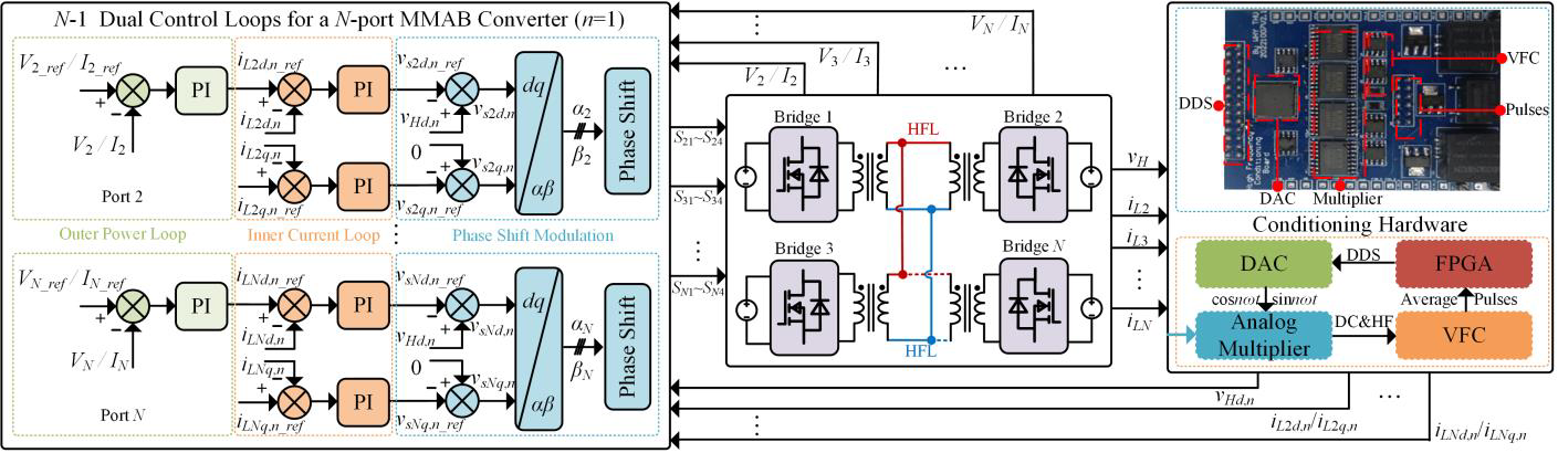
A frequency-domain model separates active power from fundamental reactive power in the common high-frequency link. Dedicated analog conditioning circuits extract the required power information from nonsinusoidal bridge voltage and current waveforms, giving the controller real-time feedback without a computationally heavy harmonic calculation.
Reactive power is a useful signal because it captures the portion of link current that oscillates between bridges without producing net dc transfer. Minimizing it reduces current stress at its source instead of relying on a detailed loss model whose parameters may change with temperature, tolerance, or aging. The challenge is that transformer waveforms are switched rather than sinusoidal, so conventional low-frequency power measurement cannot be applied directly.
The conditioning hardware isolates the fundamental voltage and current components and produces signals proportional to their phase relationship. This turns a high-bandwidth waveform calculation into a compact measurement channel that the controller can sample in real time.
Parameter-independent online optimization
The active-power loop maintains the requested energy transfer among ports, while the reactive-power loop adjusts modulation toward the minimum circulating-current condition. Because the optimum is found from measured power information, the online controller does not require accurate leakage-inductance or device-loss parameters.
The two loops have distinct responsibilities. The active-power controller rejects load and voltage disturbances so that every dc port follows its reference. The optimization loop perturbs the common phase-shift degree of freedom, observes the measured reactive-power response, and converges toward its minimum. Decoupling the objectives keeps the search from disturbing required energy transfer.
This measurement-driven approach is particularly useful when hardware differs from its design model. Leakage paths, dead time, semiconductor voltage drops, and magnetic tolerances all affect the true optimum. Because the controller observes the built converter rather than a nominal parameter set, those effects are included automatically.
Validation across operating conditions
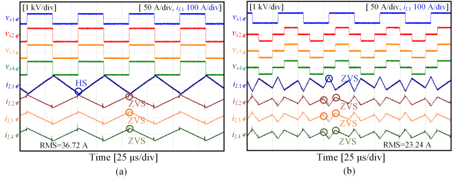
Across three test conditions, the method reduces the summed transformer-port RMS current from 36.72, 37.73, and 40.08 A under SPS to 23.24, 25.51, and 28.75 A, respectively. The measurements also confirm ZVS at every port for the evaluated cases.
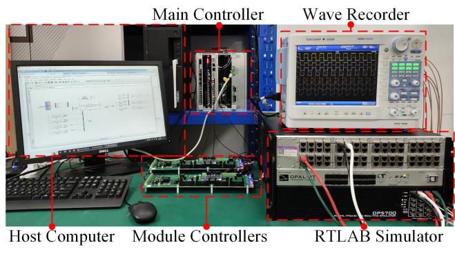
The hardware-in-the-loop tests cover steady operation and transitions between power commands. Active power continues to track its reference while the reactive loop searches for the low-current point, demonstrating that optimization does not have to pause normal operation. Consistent reductions across all three conditions also show that the method is not tied to a single voltage ratio or loading pattern.
Compared with an offline lookup table, RPOC trades some precomputed speed for adaptability. It can follow component drift and operating conditions not included during design while retaining a transparent physical objective, which is valuable in multiport systems whose power-flow combinations change over time.
Published in IEEE Journal of Emerging and Selected Topics in Industrial Electronics, vol. 5, no. 3, pp. 1333–1337, July 2024.